The fourth part of the plastic packaging container structure design and manufacturing
Chapter 1 Plastic Packaging Overview
Chapter 2 Injection and Molding Containers
Section 1 Overview of Molding Molding <br> First, the definition and characteristics of molding molding Second, the molding equipment three, the molding process
Section 2 Injection Molding
First, the definition and characteristics of injection molding Second, the main injection molding equipment
III. Injection Molding Process Section III Structural Design of Injection and Molding Containers 1. Process Requirements for Structural Design of Molded Products
At the intersection of two (or three) faces of the container, rounded corners should be designed.
1 The advantages of designing rounded corners:
a. It is beneficial to improve the flow of mold filling;
b. Eliminate stress concentration due to acute angles;
c. Extend the service life of the mold;
d. Arc transition is beautiful, and easy to eliminate dust inside.
2 value
Long bar-shaped projections on the product, usually play a role in strengthening and decorative effects:
a. Without increasing the wall thickness, improve the strength and rigidity of the container;
b. function as an auxiliary runner to improve the flow mold filling state and facilitate shaping;
c. Avoid shrinkage, air bubbles, dents, etc. due to uneven wall thickness.
There are triangles, trapezoids and circles.
3 General Principles for Reinforcing Bar Design (P142-143)
a. Can be set on the inner wall, outer wall and bottom surface;
b. Avoid and reduce the local accumulation of plastic, multiple ribs should be staggered with each other, otherwise it is easy to produce shrinkage holes,
Bubbles, cracks;
c. Reinforcement ribs must have sufficient slope, and the connection between the ribs and the container body should be rounded.
d. Designed to be short and More well;
e. Its direction should be consistent with the direction of plastic flow, otherwise it will reduce the toughness of the container 4 size design (see P143 Figure 8-44)
a. Structural dimensions (see P143, Figure 8-44);
b. If the rib thickness is equal to the wall thickness, in order to mask the defects such as dents, the design of the embossed pattern is a protruding short columnar portion on the product. Provide seats for fasteners such as structural or decorative inlays and screws. (stress and strain here) design principles
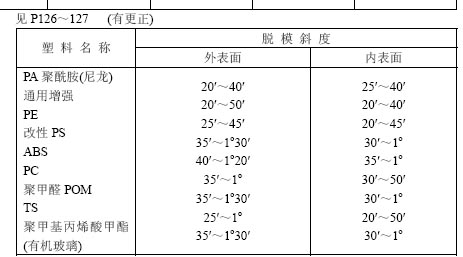
1 should have enough draft angle;
2 The junction between the root of the boss and the wall should have enough rounded corners;
3 The boss should be as close as possible to the side wall of the product, but the inner boss cannot be too close to the fillet of the side wall;
4 fine and high bosses, reinforced with ribs;
5 The outside diameter of the boss should be equal to two to three times the hole diameter, and the height should not exceed twice the outside diameter of the boss.
The gussets are located at the edge of the product and serve to support the wall surface of the product and increase the strength and stiffness of the product.
The design dimensions are shown in Figure 8-63 in P149 and are determined by the product wall thickness.
When the entire bottom surface of the container is used for support, if the bottom surface is deformed, it will be unstable. Therefore, the center of the bottom surface of the plastic container should be designed to protrude upwards or be supported by feet.
Second, the other design of the model product 1 hole type according to the relative position of the hole axis and mold opening and closing direction:
Parallel hole simple Best vertical hole complex Less inclined hole complex Avoid holes according to hole characteristics:
Through hole through the blind hole does not penetrate through the step hole The design of the recess hole hole 2 (Note):
a. The distance between the hole and the hole is more than twice the hole diameter;
b. The depth of the blind hole is limited, which is related to the hole diameter and the molding process;
c. avoid the use of shaped holes;
d. There is a limit to the distance between the hole and the edge; (P145 Figure 8-55 b)
e. The design of side holes is to simplify the mold structure and improve the strength of the container.
f. The cross-sectional hole design should increase one of the hole diameters to avoid the inconvenience caused by the eccentricity of the upper and lower holes.
1 Method for obtaining threads (machining)
Formed thread thread inserts
2 molding thread cross-section shape and application
a. Standard thread:
Fast, easy to install, etc.
b. Square thread:
With high connection strength, suitable for connecting products with high strength requirements, such as plastic pipe fittings
c. Trapezoidal thread:
Similar square thread, high connection strength, but easy to form, suitable for high strength products, such as centrifugal pump casing
d. Sawtooth thread:
The efficiency of the square thread and the strength of the V-thread are suitable for the connection of unidirectional power or unidirectional forces, e. Toothpaste tube plastic cover thread
f. Arc Thread:
The root of the thread is a circular arc that does not produce local stress concentration and can be stripped by force, such as glass bottle caps, cosmetic bottles and caps.
g. V-thread (rarely used):
Local stress concentration in the root
3 molding molding thread (three)
a. Formed with a threaded core or ring:
Can be formed at one time, and the quality is good, but when designing the thread, care should be taken to ensure that the core is separated from the product and the mold structure is complex.
b. Molding with flaps (for external threads):
The mold has a simple structure and is easy to operate. However, it has overflow edges, which are difficult to remove and affect the assembly. The accuracy is not high. Generally, it is not appropriate to use them, especially TS products.
c. Forced mold release threads (compared to TP internal threads, such as caps):
The shape of the teeth is not high and does not exceed the allowable strain rate (plastic deformation occurs)
Strain rate (%) = (thread diameter - thread diameter) / thread diameter × 100%
4 thread design
2 design considerations
a. Hinge thickness, small container thin, large container thickness, thickness <0.5mm;
b. The thickness at the hinge should be even;
c. Once formed, the hinge is a channel;
Molecular flow orientation: The molecules are aligned along the direction of motion under the action of shear forces.
Tensile orientation: molecules are aligned along the direction of force under the action of tensile forces.
After demoulding, it should be bent back and forth several times immediately to obtain the effect of stretching orientation.
1 form:
Braille: raised graphics, mold corresponding parts concave, easy processing, the word wear bad concave: graphics concave, the corresponding part of the mold convex, processing is difficult, the word wear convex word: concave convex, can be Made of inserts, often using 2 design points
a. protruding height should be greater than 0.2mm, often take 0.3 ~ 0.5mm,
b. When the line is wider than 0.3mm, often take the protrusion 0.8mm;
c. Spacing between two lines >0.4mm;
d. The embossed word border can be more than 0.5mm higher than the embossed word;
e. Stripping angle greater than 10 degrees.
Omni-Directional Barcode Scanner
Barcode Scanner,Barcode Scanner App,Barcode Scanner Iphone,Barcode Scanner Software
gfsdgsgds , http://www.nbprinters.com